
- Rig Building
- Touring Essentials
- 3.5mm
- Adapters
- Balanced/Stereo
- Bulk Product
- Digital
- DMX
- EtherCon / Ethernet
- Fiber Optic
-
Footswitch Cables
- RJM
- Bogner Amp Cables
- Egnater Cables
- Engle
- Fender Amp Cables
- Framus Cables
- G-Major
- Hughes And Kettner Cables
- Laney
- Marshall Amp Cables
- Mesa Amp Cables
- Metropoulos
- Mezzabarba
- PRS Amp Cables
- Peavey Amp Cables
- Randall Amp Cables
- Red Plate
- Rivera Cables
- Soldano Amp Cables
- VHT/Fryette
- Voodoo Lab Control Switcher Cables
- Fractal Audio
- Guitar/Line Level
- iPod/MP3
- Looms
- MIC/XLR
- Midi
- Multipin
- Patch Panels
- Power
- RCA/Phono
- Snakes
- Speaker
- Tattoo
- Video
- Wireless
- Cambium Products
How To: Build a Redundant Quad Cortex Rig (Part 2, With More MIDI!)
14 Nov 2022
How To: Build a Redundant Quad Cortex Rig (Part 2, With More MIDI!)
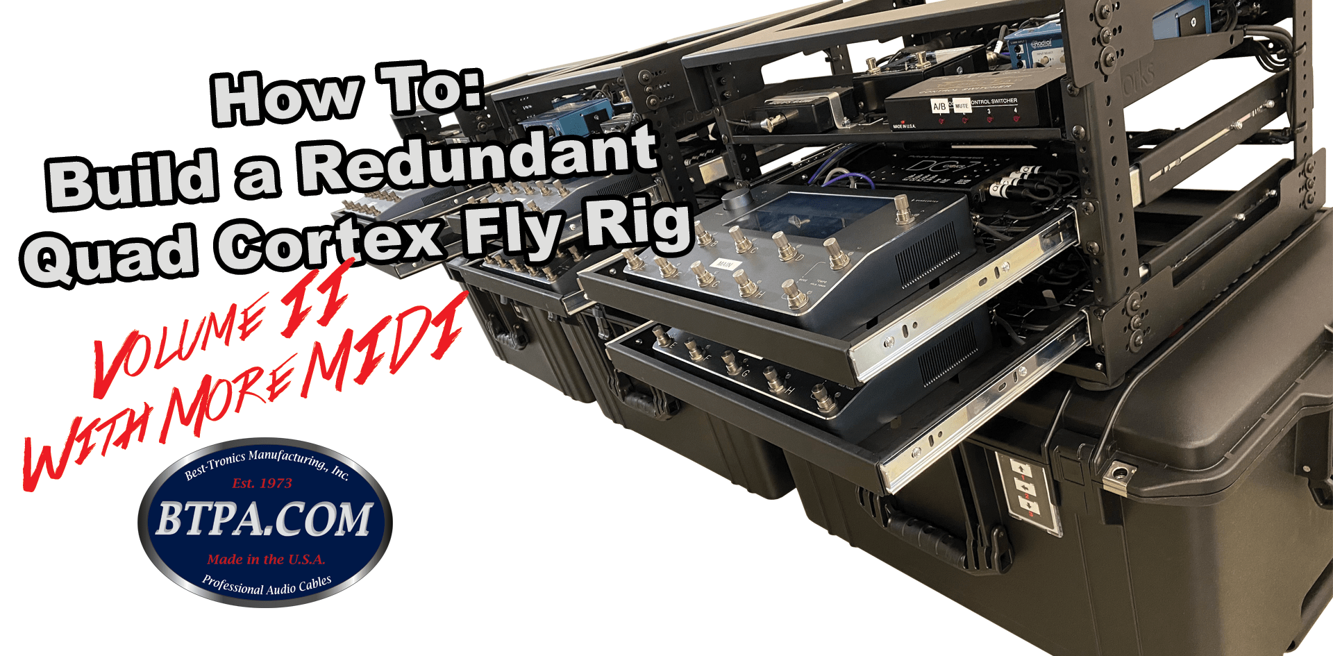
This video/tutorial takes a deeper dive into the redundant Quad Cortex racks we have been building. It focuses on MIDI controlled input switching & how to program MIDI to control the Main/Spare + A/B/C input switching.
If you are unfamiliar with what a redundant Quad Cortex rig is, or what this even means, please check out our initial video explaining this - How to build a redundant Quad Cortex Rig
The main things covered within this video are how to build this rack using MIDI controllable A/B/Y, which can also select which output (1 or 2) the inputs route to. We also cover how to MIDI program this type of rack and switch between inputs & Main/Spare Quad Cortex.
Gear Necessary:
Other than the Quad Cortex & Wireless units, here is what we are using:
- Sliding Rack shelf - Gator GRW-SHELF1SLD
- Fixed Rack Shelf - Gator GRW-SHELF1
- Fly Rack - Circle Three Designs 6U Aluminum Fly Rack
- Radial Backtrack
- Cioks DC7 Power Supply
- Voodoo Lab Control Switcher
- Lehle 3at1 SGOS
- MIDI Solutions Quadra Thru
MIDI Signal Path
Here is the route the MIDI signal takes:
- MIDI Controller/Playback Laptop/MIDI Carrier Pigeon -> MIDI In of the rack
- MIDI Input from the rack panel hits the MIDI Thru Box Input, which then splits to:
- Quad Cortex Main
- Quad Cortex Spare
- Lehle 3at1 SGOS
- Voodoo Lab Control Switcher
Defining MIDI Channels
You need to set your MIDI gear to appropriate MIDI channels. We are not covering the QC MIDI channel adjustments as that is pretty straight forward and not needed to be known for the switching within this rig. For the sake of this rig, we have the Lehle at MIDI CH 2 and Vodooo Lab Control Switcher at MIDI CH 3.
- Setting the Lehle MIDI Channel
- Remove power from the Lehle device
- Hold down left foot switch (A) and power the device up
- The lights will illuminate above switches B and C, alternating. Let go of foot switch A after the desired number of lights illuminate, dictating the MIDI channel you want. For instance, LED B illuminates, then C, and you let go. Two lights have illuminated, meaning this is MIDI channel 2.
- Setting the Voodoo Lab Control Switcher MIDI Channel
- Remove power from the Voodoo Lab Control Switcher
- Hold down button #2 and power up the unit
- LEDs will flash and then stop when you let go
- Select the corresponding LED light (as listed in the product manual) for the desired MIDI Channel. The unit comes stock on CH1, meaning no lights are illuminated.
- For the sake of this rig we want MIDI CH3 - so LED #2 is illuminated
- Disconnect from power, then re-connect.
Programming the Lehle 3at1 SGOS
To our knowledge, this device can only be controlled via PC commands.
Send a desired PC command to the Lehle. Then, hold down the desired switch until it stops flashing. The Lehle has now learned this PC command to the function you have defined. Here is an example:
For this scenario we want Input A output 1 (Green LED light) to correspond to MIDI PC 1.
- Send PC 1 from your MIDI controller to the Lehle 3at1
- No lights should be on the Lehle.
- Press and hold Footswitch A so that the green LED above it is on and green (not blue) and hold down until the LED stops flashing
- You have completed this
Programming the Voodoo Lab Control Switcher
First, you need to setup the Control Switcher to accept CC, PC, or both commands (depending on what you are using). You do this by:
- Remove power from the device
- Hold down button 3. The lights will flash until you let go
- Use buttons 1 & 2 to select the appropriate value referenced on the manual
- For this rack's purposes, we wanted CC And PC commands in case the end user wanted to use either or. We left LED 1 & 2 on.
- Unplug the Control Switcher from power
Second, the Radial Backtrack unit's CH A/B relay is set in reverse polarity. You need to adjust the Control Switcher to accommodate for this.
- Remove power from the device
- Hold down button 1 while powering up. The lights will flash until you let go
- Press the button that the TIP signal from the backtrack is hitting so that light is on. In this case, it is switch 1 on the control switcher.
- Unplug the power from the Control Switcher
Now, we are ready to program. For the sake of this rack we are showing how to do this with CC commands.
On your MIDI Controller, send CC commands corresponding to the desired switch you want to control to the Control Switcher's MIDI Channel (CH3 in this case). Default, the CC group is 80-83. 80 controls switch 1, 81 controls switch 2, and so on and so forth. For values, we use 0 for off and 120 for on. For example:
You want to switch to output B on the Radial Backtrack. You will send CC Command 80 (switch 1) with value 120 to illuminate the LED, this switching the Backtrack to "B".
Comments